
The 150 ton Field Monitor
The 150 ton Field Monitor was a product of America’s growing industrial might, as well as the republic’s anticipation in becoming involved in the First World War.
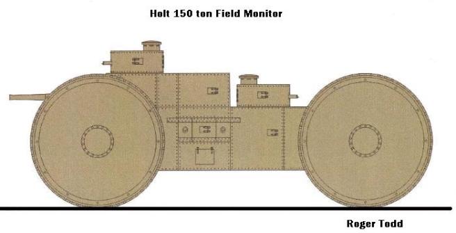
The 150 ton Field Monitor design has its origins with the designers of the Holt Steam Wheeled Tank, this being their initial design. Optimism in the States for the Big Wheel theory was still quite high, even though America had all sorts of tracked machines to experiment on. The designers chose to use two huge pairs of wheels, forward and aft, powered by two large steam engines, presumably designed by Holt, with the help of engineers from Doble, most likely their chief engineer, Abner Doble, who had designed the engine for the Holt Steam Wheeled Tank.
The Field Monitor was essentially a huge version of the Holt Steam Wheeled Tank, with four 20 foot tall wheels. Unlike the Holt Steam Wheeled Tank, the Field Monitor did not have a steering wheel in the rear, instead it had two of the four 20 foot wheels. Each wheel had an individual gear box, connected to a central transmission. The transmission was connected to the two steam engines, located in the center of the Field Monitor.
It was to carry two American six inch naval guns, arranged side by side in the front, in the same arrangement as the Holt Steam Wheeled Tank’s 2.95″ (75 mm) mountain gun. (The six inch was a secondary armament for most American ships at this time.)
In the five and six-inch guns that could sourced from the Coast Artillery and the reserve store of the Navy there was shell power that might quickly be made available for the western front. When the United States entered the war the Ordnance Department at once set out to master the problem of placing these heavy fixed emplacement pieces on mobile field mounts. An inventory showed that ninety-five six-inch and twenty-eight 5-inch guns could be secured from the Coast Artillery and forty-six 6-inch guns from the Navy, while an additional 30 guns of the six-inch size were offered by a private dealer in this country. {These guns were shipped to the Holt manufacturing plant; to be used in various forms, such as Mobile tracked artillery, as well as Tank production. Such as the 150 ton Field Monitor and the 1500 ton Land dreadnought}
Minor alterations were necessary in many of the guns to make them adaptable to field mounts, and the Navy guns, ranging from 30 to 50 calibers in length, had to be cut down to a uniform length of 30 calibers. The long six-inch seacoast guns were not shortened because it was planned to return them to the Coast Defenses from which they were taken. Speed in the manufacture of the Carriages for these Guns demanded that they be of the simplest design consistent with the great strength necessary to bear the weight of this fixed emplacement material. The carriage designed for the five and six-inch naval guns having been placed under test and found to meet all requirements by September of 1917 and orders were placed for ninety-two 6-inch Carriages and twenty-eight five-inch Carriages.
Owing to the great weight of the long six-inch seacoast guns, however it was found at that it would be necessary to carry them separately on big transport wagons. Such a wagon was designed and an order placed for 55 wagons in February of 1918.When the Armistice was signed practically all of these mounts had been completed. Seventy-two entirely assembled six-inch units and twenty-six; five-inch units had been shipped for overseas duty.
Secondary armament was to be 10 Colt Model 1895 Machine Guns, (Potato Diggers) currently being used in Mexico. (The Colt-Browning M1895 was one of the first “successful” gas operated machine guns designed by John Moses Browning. It was offered to Colt by Browning in November 1890. Originally chambered for .30-40 Krag, rebarreled and rechambered versions in 30-06 Springfield were designated M1895/1914. It became the first automatic machine gun adopted by the United States and saw limited use in the Spanish-American War and the First World War.)
The M1917 Browning Machine guns would later replace the Colts, after the United States adopted the M1917 as there main machine gun in late 1917. (The M1917 saw limited service in the latter days of the First World War. Because of production delays, only about 1,200 Model 1917s saw combat in the conflict, and then only in the last two and a half months of the war. They equipped about a third of the divisions sent to France; the others were equipped equally with machine guns bought from the French or the British Vickers machine guns built by Colt in the US. Where the Model 1917 did see action, its rate of fire and reliability were highly effective.)
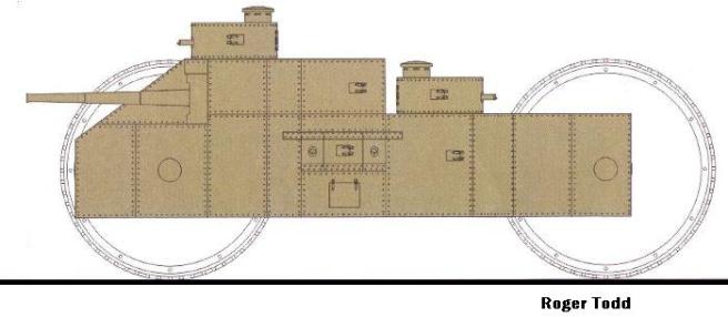
The Field Monitor would carry two machine guns in each turret, located at the front, above the main guns, above the driver’s and commander’s position, as well as one at the rear between the large Wheels.
According to the design notes by Holt, the machine gun turrets would have had limited transverse due to being placed between the large steel wheels. The arcs of fire were only 20% front, 10% at the rear. With only roughly 2 to 4% per side, only if the Monitor was still, 0% if moving. [Note: should these figures be angles, or are they describing the percentage of area covered at each side?]
Unfortunately, this design never left the drawing board and, like many other war designs, has faded from memory. Due to its weight and bulkiness, and unorthodox running system, it is most likely the 150 ton Field Monitor would have been a dismal failure. Of course, that is just one’s opinion.
Armament:
Two Naval 6inch Guns.
Ten Colt-Browning Model 1895 Machine Guns, later Browning M1917 Machine Guns.
Armor: 24″ to 70″.
Weight: estimated at 150 tons.
Crew: 20
The 200 ton Trench Destroyer
The 200 ton Trench Destroyer was yet another American tank design of the First World War, dedicated to the task of rolling across the Western Front in pursuit of the Hun, though ultimately tossed aside for a more reasonable solution. As stated above, America’s industrial might was attaining new heights during this time, and the design grew out of many put forth by all manner of inventors, trying their best to aid the war effort, and of course make a little money (when opportunity knocks).
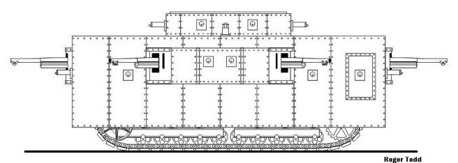
This design, although enormous, a Behemoth in proportions to the tanks currently on the battlefields in Europe, was quite sophisticated inside, while the outside resembled a huge disfigured A7V, brisling with six times the firepower of the German machine.
The chassis was enormous, and was originally slated to be used as the basis of a large excavating machine. The design for the track system was designed by the brilliant Pliny Holt and Elmer Wickersham (the latter of land torpedo fame). Their design for the excavating machine grew out of the need for heavy earth-moving machinery during the colossal undertaking of the Great Dig, the Panama Canal. Although opened in 1914, by late 1917 there was already a need for the canal to be widened. But this would have to take a back seat as long as the War raged in Europe, for fear of sabotage. The design had its origins in late 1915 at which time, of course, there was no thought of the machine being used in a military role.
The track system was huge, twice the size of the A7V to which it bore a marked resemblance. From the photo you can discern the embryonic excavating equipment, which had already started to be placed on the chassis. Most of this equipment, of course, was removed to make room for the enormous amount of firepower the Trench Destroyer was to be fitted with.
No definitive information exists on the type and size of the engine or transmission used. The only information states it was to run on petrol. No dimensions have been unearthed except for the two different descriptions of the Commander’s area on top of the Trench Destroyer, both being provided from two different Patton resources.
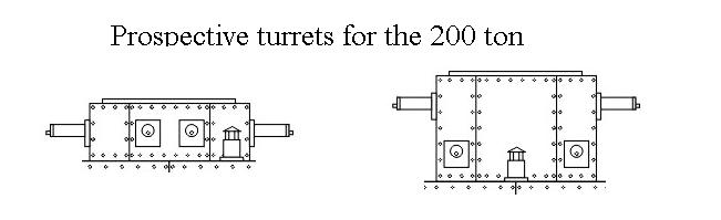
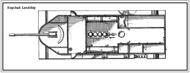
As a twist to this story, a Canadian by the name of Stephen Kupchack, who happened to be one of the hull designers for the Trench Destroyer, designed an Armored Vehicle based on the 200 toner Trench Destroyer. {After the idea was laid to rest, building the enormous Trench Destroyer.} Mr. Kupchack submitted his design to the English War Office in late 1918, and it was dully dismissed, after the War Office asked Mr. Kupchack to produce a full size machine for demonstration purposes. They offered no financial service to accomplish this.
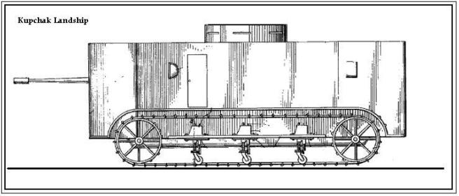
Without the backing of Holt, Mr. Kupchack’s design had a very feeble track design, which would possibly have been too weak, even if he could have built a full size model. His armament was also scaled down. The drawing does not represent any specific piece of armament; Mr. Kupchack took the liberty of drawing a resemblance to no specific piece, known at the time. He had no connections, to be able to fit his Armored Vehicle with any form of weaponry. This was a huge hindrance, but he was hopeful, if the War Office liked his design, and backed him financially, he could rely on them to supply the armaments.
This of course did not materialize, the fate of many other designs for Landships at this time which simply fell through the cracks.
The following are quotes from different Patton Resources, describing his involvement with the 200 ton Trench Destroyer. The following is a quote by General Patton, from the book Treat ’Em Rough, Describing the 200 ton Trench Destroyer. This of course is in the 1940s, as he writes down information for his War Memoirs.
“While in France in 1918, I was directed to report on the military value of a machine going by the euphonious name of the “moving fort and trench destroyer”. An elaborate set of blueprints accompanied the description of the horrid instrument. Those prints depicted a caterpillar propelled box of generous proportions covered with two inch armor and bearing in its bosom six “75s”, 20 machine guns, and a flame thrower while in the middle was a rectangular box 6x3x2 feet in size with the pathetic epitaph “engine not yet devised”. I do not know if atom bursting was known at that date, but if it was, I feel certain that an engine actuated by that sort of power must have been intended as no other form of power occupying so small a space could have propelled the 200 tons of estimated weight of the “fort”.”
The following is how Patton describes the 200 ton Trench Destroyer in his personal WW1 papers. Dated 1918 Patton Papers P A 198.
- “I have been given a task to report on the military value of a set of plans containing an enormous machine; by the name of “Moving Fort or Trench Destroyer””. “I believe the dubious name of Moving Fort should be given to the 1500 ton monstrosity that we also discussed today.”
- “The prints depict a caterpillar propelled box of generous proportions covered with two inch armor and bearing in its bosom six French 75s, and openings for at least 20 machine guns. On the top is located abox 6 x 5 x 4 feet, {6x3x2 Was quoted from Treat ’Em Rough} housing machine guns, and the commander’s location. The Trench Destroyer looks in my opinion similar to the German so called A7V but twice as large.”
- “Entrance in to the beast is from the rear via twin armored doors on either side of the 75. The inside is crammed full of equipment, men and weapons. I have been informed one track assembly has been converted by a tractor firm in the states to build a mock up, for evaluations. It is to be shipped to France in July (1918) “{This of course never materialized}
- “The estimated weight is between 180 and 200 tons, I am dully aware; this monstrosity will have a rough time of it passing through villages to get to the front. G.Rockenbach has informed me, that the US needs to step up on its tank designs, and this may be a possible ending to the US requiring the aid of its allies to provide tanks.”
The known projected weight for the Holt excavating machine was to be around 60 tons. Extremely large for the time, taking into acco
unt the weight of the weaponry, the large amounts of armor, and its capacity for 30 men, this would possibly have been an extremely formidable Armored Vehicle. Little else is known about these beasts of the Great War, except even their formidable size is diminutive compared to other designs of the same time period, like the 1500 ton Massive Leviathan, designed to crush armies and cities into oblivion, and the Shuman Land Battleship, amply called the “Superdreadnought” with 200 foot wheels. The story only begins.
Armament
Six 75 mm cannons, They were actually the famous French Canon de 75, modèle 1897s.
Twenty M1917 Browning Machine Guns.
One Flame Projector, Tractor Type, Mark I
Crew: 30
Weight: 180 to 200 tons
- Treat ’Em Rough by Dale E. Wilson
- Patton Papers, Memories of the Great War. 1919 (1-4)
- Holt Digest, Volume 3, Volume 8, 1917-1918 respectively.
- Rockenbach Papers. Volume 5 Great War 1921
- Pliny E. Holt, Memoirs of a Pioneer 1930
- Military Might of the Industrial Nation, 1916-1921 By Langford Stevenson 1923.